
- DigiMAX - Digital mode interface -
2025.11.01 Update! NEW Version!
You find the latest update on the 'DigiMAX v.2' page. (Text only in Swedish)
Du hittar de senaste uppdateringarna på 'DigiMAX v.2' sidan.


DigiMAX v.2 KiCAD PCB layout / 3D-Vy
DigiMAX the complete SOUND / PTT / CI-V Level Rig2pc interface for digital modes, with the folowing functions.
This information is now also available in Swedish. --> Svensk instruktion (565Kb .pdf file)
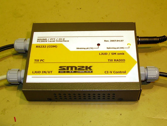
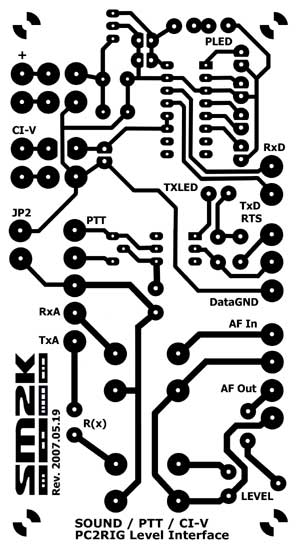
- Front panel -
DigiMAX - Revision 2007.05.19 Changed pcb layout, it's now a little smaller to fit into the new box. Also got a 'power led' and a new 'Front' panel layout. The PCB Layout files is updated to rev. 2007.05.19
- Making the DigiMAX interface -
Here is a complete description of the interface, with schematics, PCB-Layout and component list. ready for you to use free of charge!
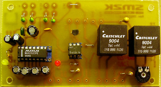
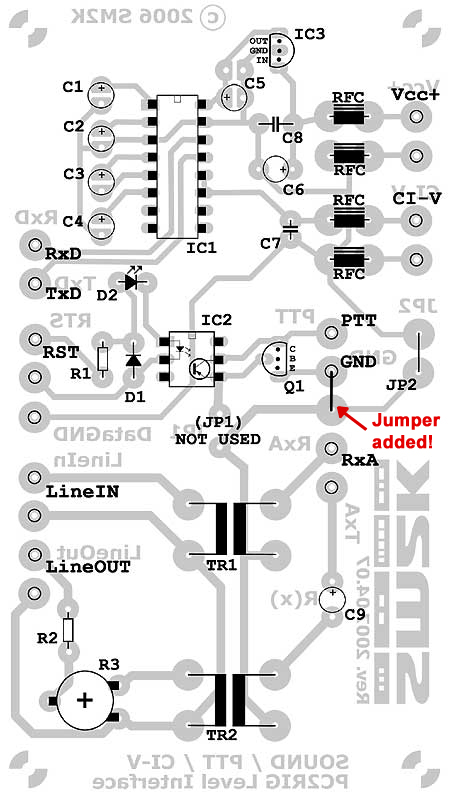
Closeup of DigiMAX PCB component side. rev. 2007.05.19
Closeup of BCB component side. rev. 2007.05.19
You can read more about making your own printed circuit boards -->Here!
- Chematics / Components -
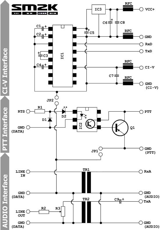
Interface chematics. (OLD VERSION)
CI-V interface part
=======================
IC1         MAX232     RS-232 level converter
IC3         78L05      5Volt regulator
C1-C6       22uF/16V   Electrolytic
C7          100pF      Cheramic
C8          4,7nF      Cheramic
RFC         1uH

PTT interface part
=======================
IC2         4N33       OPTO Coupler
Q1          2N3904     (Or equal, only needed if ptt current exeed 60mA)
D1          1N4148     Diode
D2          LED        PTT indicator
R1          Xohm      (use if needed to reduce levels)

Soundcard interface part
=======================
TR1-TR2     1:1/600ohm Audio isolation transformer
C9          3,3uF/25V  Tantal
R2          Xohm       (use if needed to reduce levels)
R3          100Kohm    Trim potentiometer
- PCB Layout -
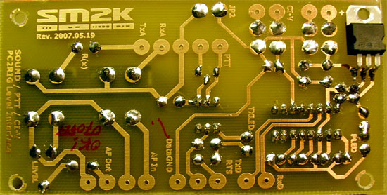
This is the latest PCB layout files. rev. 2007.05.19
SOUND/PTT/CI-V PCB size is 110 x 60 millimeter - Layout in High resolution rev. 2007.05.19
(Ready to print on 115x65mm board)
In addition there is also a layout for a 'PC-Sound to RIG interface only' available on the 'Old page' if the CI-V part's not needed
You can read more about making your own printed circuit boards -->Here!
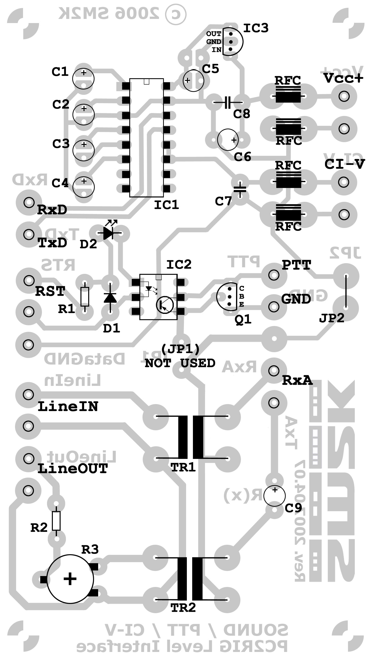
- Component placement -
This is the PCB with the corrected layout with C6 and C8 in the correct places. (PLED is missing in this drawing. Refere to images of component side for component placement)
Component side of PCB with component placement (OLD VERSION)
Component placement - High resulotion (330K .pdf file)
- Internal wire hookup -
Drawing of the internal wire hookup to transceiver (TRCV) and PC
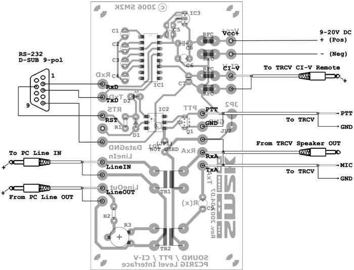
Internal wire hookup (OLD VERSION)
RS232 CABLE Hookup
=======================
RED      RXD (DB9 Pin 2)
YELLOW   TXD (DB9 Pin 3)
BLUE     RST (DB9 Pin 7)
GREEN    GND (DB9 Pin 5)
SHEELD   GND (DB9 connector)

RADIO CABLE Hookup
=======================
CI-V BLACK (To Center pin on 3,5mm plug)
PTT  WHITE (To pin 3 on DIN plug)
TXA  RED   (To pin 4 on DIN plug)
RXA  GREEN (To pin 5 on DIN plug)
SHEELD/GND (To pin 2 on DIN plug)
SHEELD/GND (To sleewe on 3,5mm plug)
- Honors to the brains behind -
Usually the information about almost anything is to be found on the internet;-), this is also the case for this interface. Here is some links to pages that helped me to get 'inspiration' for this project.
DF4OR Ekki's exelent page about making a CI-V interface
K4ABT Buck's disassembly of the 'RASCAL' SoundCard interface
HB9DRV Simon, author of the 'HamRadio Deluxe' software @ http://www.hb9drv.ch/
Read more...
Ham radio software i currently use. --> Read more!
Building a silent computer for my radio shack. --> Read more!
Go Back!
©1999-2006 SM2YER Goran