
- New WEB-Page -
2007.05.28 New revision of the interface is available -->Here!
- OUTDATED INFORMATION!!!!! -
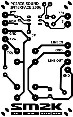
- SOUND / PTT / CI-V Level pc2rig interface -
This is a complete Rig2pc interface with the folowing functions.
In addition there is also a layout for a 'PC-Sound to RIG interface only' available when the CI-V part's not needed.
Ready made interface, toggled to TX...
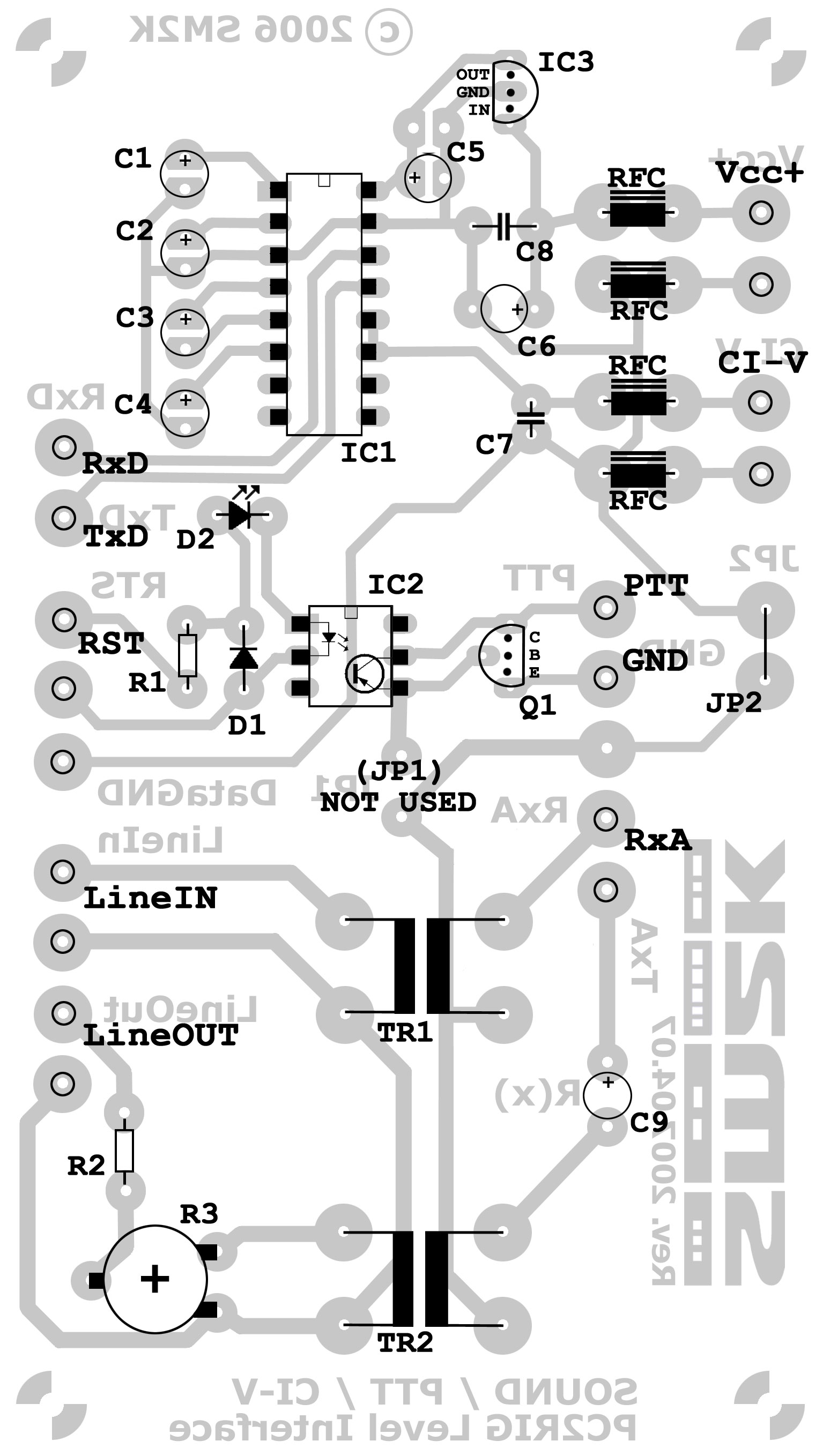
- Component placement -
2007.04.08 Added this drawing of component side on PCB with component placement. This is the PCB with the corrected layout with C6 and C8 in the correct places.
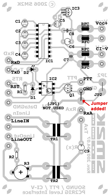
Component side of PCB with component placement
Component placement - High resulotion (330K .pdf file)
- Cable hookup -
2007.04.08 Added this drawing of the cable hookup to transceiver (TRCV) and PC
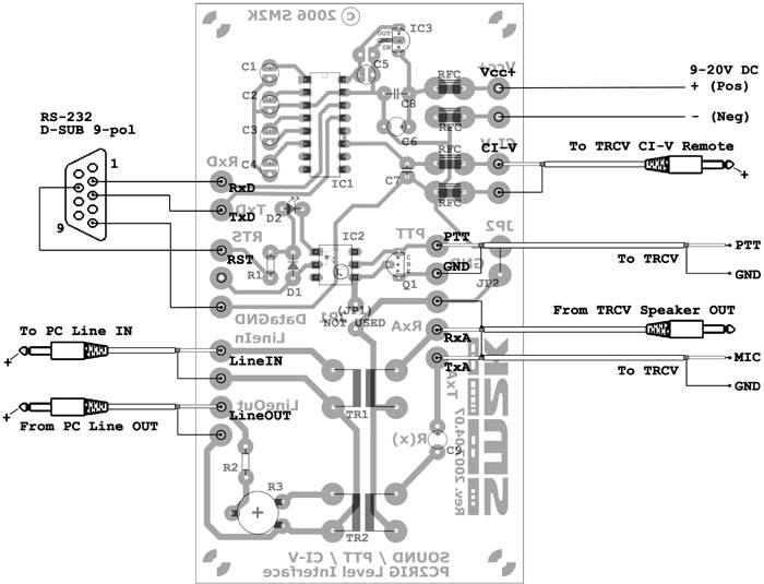
Cable hookup
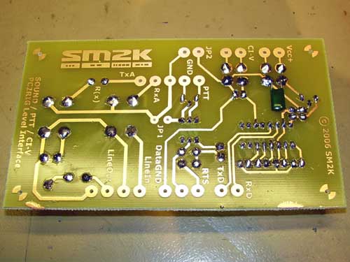
2007.04.07 Finaly updated the PCB-Layout to correct some errors with the missing places for C6 and C8.
At first i didn't have a power switch for the VCC+ so my interface was always ON,- this is not good, since the RTS signal is going up 2x3 times on every PC Boot.... This makes the Tranceiver to hit the PTT!!! -
I'm now also uses two com ports on the computer,- one for the rig control (Com1) and one only for the RST signal (Com8) This make it possible to use rigcontrole at the same time i'm running MixW usin the PTT(RST signal) for PTT-Line in digital modes.
Also made some modifications to the interface today. Since my power source is quite high in output voltage,- About 22v DC. The voltage regulator 78L05 is running warm. I replaced it with a L7805CV placed on the back side of the board and in physical contact to the metal case for cooling. Refere to images for details.
L7805CV regulator on the backside of the board
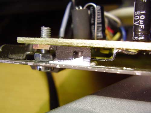
L7805CV regulator with surface contact with cased
2006.10.01 Now trying to run the psk31 function in the HamRadio Deluxe software bundle, starting to get the grip of it now. Info about the software is to be found @ http://www.hb9drv.ch/
Notice a problem when running rig control and psk31 software at the same time, the com port is occupied by the first software started. Maby i need to get the RTS signal for the PTT function from another com port?? It should not be to hard to accomplish cince the interface is built up by separate functions.
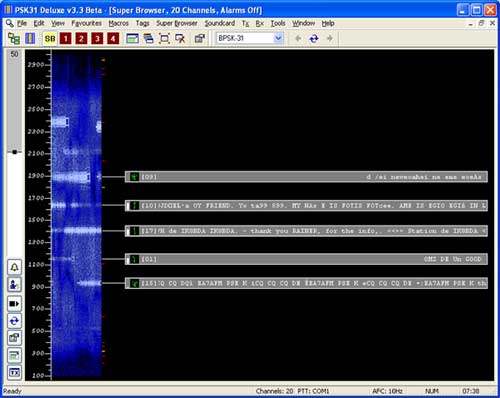
Screen dump from HamRadio Deluxe psk31 'SuperBrowser' screen
2006.09.30 Made my first PSK31 QSO with the interface, worked ON5KJK Jaques on 14.070MHz. The interface is working fine, adjusted levels according to DigiPan manual. I'm using 'DigiPan' Software for PSK31 and HamRadio Deluxe for rig controle, i think it's better to use only HamRadio Deluxe also for PSK31 but i can't get it to work as well as DigiPan.
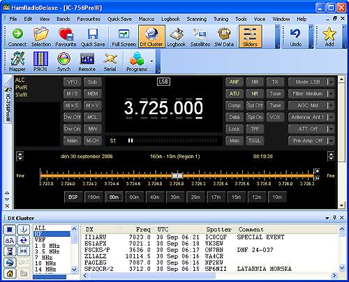
Screen dump from HamRadio Deluxe rig control screen
2006.09.26 The interface is now tested and working, i'm only using one cable (4wire +sheild) to connect to the radio, this does that i needed to short 'JP1' and 'JP2' and the ground side to the PTT transistor in order to get ground levels to al functions. SOUND/PTT and CI-V. I'm about to add some drawings / images of the hoockup.
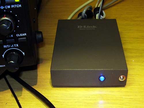
2006.09.24 About to hookup the interface for some initial tests, interface ready wired in the box and ready to go! Used a scrapped metal box from a 'DLink' fiber-optic converter. Box size is 88(W) x 25(H) x 120(D) millimeter.
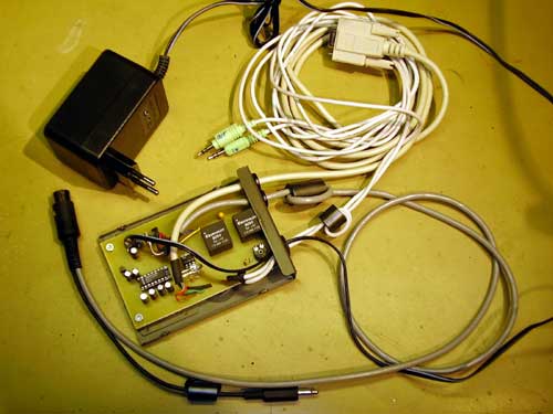
The interface in the box, i use ferrite beads on al cables.
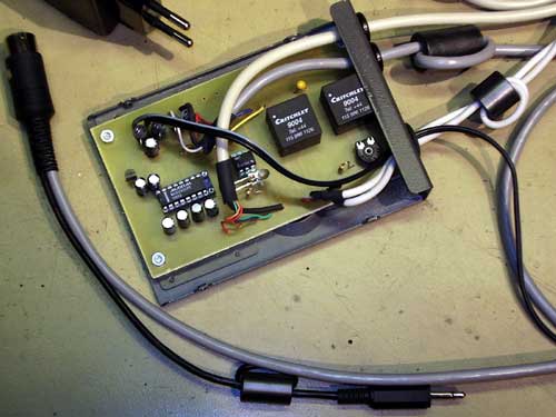
The interface in the box - Closeup
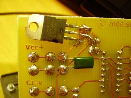
2006.09.11 Made the printed circuit board this weekend, mounted the components and discovered som minor errors on the layout, they may be used but as shown on the photos, some components have to go in some strange places :-) - I'm about tho change them, but there is so much to do, and so little time.
NOTE! As of 2007-04.07 the PCB layout is updated! The errors is no longer present!
If you look on the images of the readymade board the two condensators is soldered 'in strange places' C8 on the back of the board and C6 squeezed in the same holes as the RFC's on the component side,- so the interface works just fine with this 'mods' !!!
Final testing is pending, i return with some results a.s.a.p. Circuit drawings is also in the 'making'.
You can read more about making your own printed circuit boards -->Here!
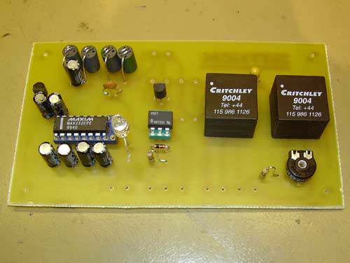
Mounted PCB component side (**Unchanged layout)
Mounted PCB Solder side (**Unchanged layout)
- Chematics / Components -
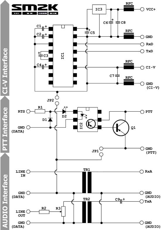
Interface chematics
CI-V interface part
=======================
IC1         MAX232CPE  Dual RS-232 level converter
IC3         78L05      5Volt regulator
C1-C6       22uF/16V   Electrolytic
C7          100pF      Cheramic
C8          4,7nF      Cheramic
RFC         1uH

PTT interface part
=======================
IC2         4N33       OPTO Coupler
Q1          2N3904     (Or equal, only needed if ptt current exeed 60mA)
D1          1N4148     Diode
D2          LED        PTT indicator
R1          Xohm      (use if needed to reduce levels)

Soundcard interface part
=======================
TR1-TR2     1:1/600ohm Audio isolation transformer
C9          3,3uF/25V  Tantal
R2          Xohm       (use if needed to reduce levels)
R3          100Kohm    Trim potentiometer
- PCB Layout -
There is some minor errors in this layout, they may be used but as shown on above photos, some components have to be added to 'wrong' places:-) - I'm about tho change them, but there is so much to do, and so little time...
There is 2 errors,- no place (Pads and mounting holes) for the components c6 and c8, thay should go from +12(VCC+) to ground on the lead going from the RFC to the 5V regulator.
If you look on the images of the readymade board the two condensators is soldered 'in strange places' C8 on the back of the board and C6 squeezed in the same holes as the RFC's on the component side,- so the interface works just fine with this 'mods' !!!
NOTE! As of 2007-04.07 the PCB layout is updated! The errors is no longer present!
SOUND/PTT PCB size is 80 x 50 millimeter - Layout in High resolution
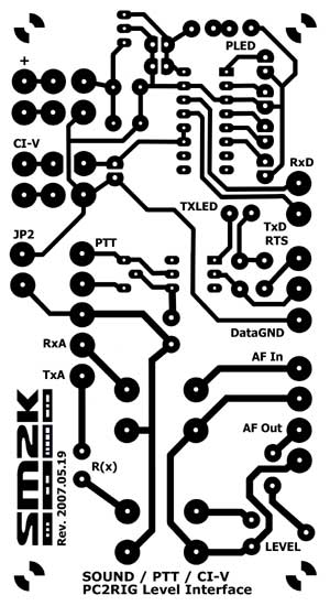
SOUND/PTT/CI-V PCB size is 110 x 60 millimeter - Layout in High resolution
NOTE! As of 2007.04.07 This is the updated / correct layout / Latest rev is 2007.05.19
- Making the interface -
(Ready to print on 80x50mm board)
(Ready to print on 115x65mm board)
You can read more about making your own printed circuit boards -->Here!
- Honors to the brains behind -
Usually the information about almost anything is to be found on the internet;-), this is also the case for this interface. Here is some links to pages that helped me to get 'inspiration' for this project.
DF4OR Ekki's exelent page about making a CI-V interface
K4ABT Buck's disassembly of the 'RASCAL' SoundCard interface
HB9DRV Simon, author of the 'HamRadio Deluxe' software @ http://www.hb9drv.ch/
Read more...
Ham radio software i currently use. --> Read more!
Building a silent computer for my radio shack. --> Read more!
Go Back!
©1999-2006 SM2YER Goran