
- Output modification for the HR2510 -
The idea of this modification is to replace the Final Power transistor, Using Motorola MRF455 - Doing this gives you some advantages.
Transistor data for the Motorola MRF455 RF Power Transistor (in 76Kb .pdf file)
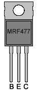
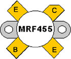
MRF477 and MRF455 is quite different!!!
- MRF477 vs. MRF455 Pinout -
These 'pinout' images illustrates the problem using the MRF455 transistor in replacement of the original MRF477,- You need to mount the MRF455 Transistor to the heat-sink and make connections to the pcb using tree short 'hookup' wires. Se also the illustration below.
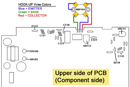
MRF455 Hookup wires and HR2510 Main-PCB connections
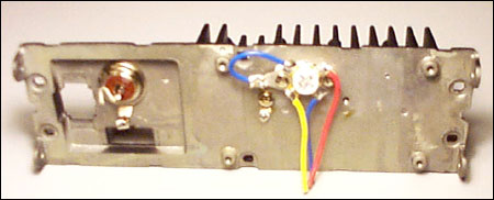
HR2510 Heatsink with Final Transistor MRF455 Mounted
The above image shows the HR2510 Heatsink with the MRF455 and hookup wires mounted on it,- I de-assembled the Heatsink to be able to drill the screew-holes to me able to mount the MRF455 transistor,- Se also the drill-diagram below.
- 2SC2086 vs. NTE-340 Pinout -
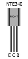
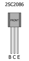
This mode also require that you replace the Pre-driver Transistor Q134, NOTE! the NTE340 use a different pin-out, simply turn the transistor 180dgr when putting it in place.
Both transistors use the TO92 Case, But the NTE340 is named 'TO92 Giant' because it is a bit longer on the top.
Comparative Transistor data
Transistor   Type    Descriprion
NTE340       Si-NPN  RF-Power/Tr, 86V, 500mA PQ=0,6W
2SC2086      Si-NPN  RF-Power/Tr, 75V, 1A, PQ=0,45W(27Mhz)
- PROCEDURE -
Output power mod for the Uniden HR2510 & HR2600

Uniden's HR2510 & HR2600 10 Meter Amateur radio's are nice for
single band operation, but a little more output power is desirable
for portable use.

CREDITS:
M.T. Stacey KC4HGH in Septembers issue of 73 Amateur Radio (1989)
Published his findings on power modifications to the HR2510.

The modifications that follow are based on his works with some
additions:

INTRO:
The factory has the HR2510 & HR2600 output power levels set for
continuous duty. I.E. AM,FM & CW 10 Watts, SSB - 20/25 Watts.
The radio is capable of much more output power for intermittent
operation like SSB.

************************* POWER MOD ***************************

  PROCEDURE                    HR2510             HR2600
---------------------------------------------------------------

Relocate capacitors to         C122,C116          C122,C116
bottom of Board. (This
is to allow spreading of
the tuned/trap output
coils.

Replace Pre-driver Tx
(2SC2086D) w/ ECG-340          Q134                Q34
(Note pinout change)
2510/2600's w/ the
2SC1973 device require
no pinout change.

Replace output Transistor
Q133 the MRF477 w/ MRF455
use short hookup vires as
described above                Q132                Q32

Replace Bias current           R158                R158
limiting resistor from
82 ohms to 68 ohms
1/2 watt device.

Pull bias jumper board
out of the circuit.            PB100               PB100
Place a current meter
(100ma) between pins
TP2 and TP4

Adjust Final bias for
80-85 MA, USB position.        VR112               VR13
No Modulation.

Fire radio up with
power meter and 100W
dummy load attached.
Adjust ALC for Maximum.        VR104               VR5
1Khz tone is helpful.

Mode to AM/FM
Spread coils                   L121,L123           L14,L16
for maximum.

AM/FM power adjustment,
20 Watts is easily obtained.
I think 25/30 may be pushing
it in this Mode. (Melt Down.)
Adjust controls for your       VR103,VR107         VR4,VR8
desired levels.

**************************************************************

My experience in increased output levels are as follows:
"SSB Mode."

HR2510 = 32 Watts RMS (1Khz Tone) / 45.2 Watts PEP

HR2600 = 37 Watts RMS (1Khz Tone) / 52.3 Watts PEP

The above measurements are made with Bird 43 into a 50 ohm load.

PARTS SOURCE:

PF PARTS INC.
1320 Grand Ave.
San Marcos CA. 92069
800-854-1927
*** End of page ***
<--Back