
Interference HOW-TO
Page 1 - Page 2 - Page 3 - Page 4 - Page 5 - Page 6
Propper installation
This page Covers How-To install your equipment properly to avoid causing unintentional interference to your neighbours. (And other Radio-Friends on the HAM band in general)
Propper installation is the first object.
Make shure to select a sutable station location within your house or apartment
- You should have access to grounded wall outlet close by, avoid long extention power-cables.
- Trye to avoid getting close to any cables or connections for television antennas / cable tv or telephones.
- Dont tangle or mix television / telephone cables with cables to / from your Transceiver transmitter.
Cables and Connections
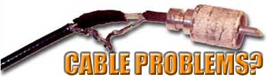
Does your antenna cable connections look like this?
Next step is to check your Antenna cables and connections.
The easy way is to use pre-fabricated 'RG-58' Coaxial-cables between your radio and amplifiers / LOW-PASS filter / switches a.s.o. This is often the best and easy way to get propper connections inside your radio-shack.
When it comes to the coaxial-cable going up to your antennas, your however forced to do some job yourself,- here is some easy steps to make propper coaxial-cable connections.
- RG-8(RG-213) Coaxial cable with PL259 Connector -
- Step 1 -
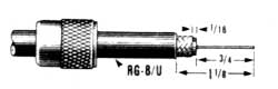
Strip jacket away. Don't cut the braid(Shield)
Cut away some of the braid(Shield), Strip some of the dielectric.
prepare exposed braid(shield) and center conductor with solder tin.
Slide coupling ring on to the cable.
- Step 2 -
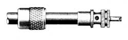
Screw connector body on to the cable.
Solder braid(Shield) through solder holes on connector body.
Solder center conductor to center contact.
- Step 3 -
Screw coupling ring back on to the connector body.
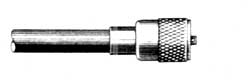
- RG-58 Coaxial cable with PL259 Connector -
RG-58 Coaxial cable is often used to connect different radio equipment together inside the shack,- if used as antenna cable,- it should not get to long,- not more than 10-15 meter maximum.
- Step 1 -
Strip jacket away. Don't cut the braid(Shield)
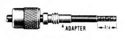
Slide coupling ring and reduction adapter on to the cable.
- Step 2 -
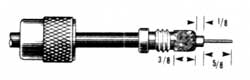
Fan out braid(Sheild) slightly, fold back over the reduction adapter.
Strip dielectric and prepare exposed braid(shield) and center conductor with solder tin.
- Step 3 -
Screw connector body on to the reduction adapter.
Solder braid(Shield) through solder holes on connector body.
Solder center conductor to center contact.
Screw coupling ring back on to the connector body.
Grounding
Propper grounding also help avoiding interferance and also give less problems with static-interferance in your reception. Please refere to the complete 'Grounding HOW-TO'
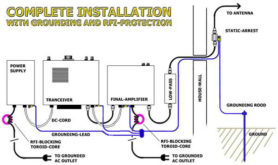
Complete installation. Read also the 'Grounding HOW-TO'
Page 1 - Page 2 - Page 3 - Page 4 - Page 5 - Page 6
*** End of page ***
<--Back