
- Digital Signal Processing -
 Introduction
In General 'Digital signal processing' is about manipulating AF and/or MF signals to inprove readability of any voice / morse or data signal. The DSP-device is mainly a micro-processor with specialy designed software. A DSP makes use of computer controled digital signal processing technology to reduce Random/Tone and Noice interferance in incoming signals. It implement the computer controled algorithms to perform its functions.
Normaly a DSP-Unit perform four different types of basic functions
1) PASS-BAND Filtering - QRM/Noice reduction by restriction of Audio band-width
2) Random Noice Reduction - Static / Pulse noice reduction
3) Notch Filtering - Automatic Multiple Notch Filtering of unwanted Heterodynes
4) Remodulation
- How the DSP works
The signal is feed into the device and the characteristic of the signal and noise is analyced using a method called 'correlation'. The DSP measures degree of correlation and filters out wanted signals from noise and Heterodyne tones, this is all done in 'real-time'.
The DSP process - DSP enhancement is basically a four-step process. Audio input is sampled several thousands of timed per second, the frequency and amplitude of the audio-signal is converted into a digital representation of the analog waveform by the A/D (Analog-to-digital) converter, the result is an digital bitstream of raw data that can be analyced and processed by the Digital signal processor.
Notch Filtering - With the notch (multiple notch), DSP circuitry examines the AF passband and the correlation of the signals present. After correlation parameters are compared, un modulated signals (heterodynes) are identified and filtered out using Narrow-band attenuations,- That is a 'notch-filter' at center of heterodyne frequencies. As the DSP dynamically checked the audio-signal in the pass-band, new heterodynes will be identified and automatically notched out, one by one, as they appear!.
DSP and CB/HAM usage
Over to the practical use and DSP-Implemetations. The Digital Signal Processing devices can be devided into tree major categories.
- Built in Digital Signal Processors (Modern HF-Radios)
- External Hardware Digital Signal Processors
- PC Software Digital Signal Processors
- Audio Spectrum analyses
To illustrate what the DSP does with the Audio signal,- i cut and paste 'screen-shots' from the spectrum-analyse window in the DSP-Filter software,- this is to get real readout of the audio spectrum after the actual DSP Processing,- when testing the software is set to 'TH' thru mode for the audio to pass strait thru (Except when getting screen-shots when DSP Filter v1.11 at work in the last section)
- PURE NOICE
This is what we start with,- pure 'pink-noice' from the radio RX-Audio.
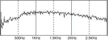
Audio OUTPUT when no DSP is active
- HETERODYNE
To illustrate the Auto-Notch filter i inject a simulated heterodyne from a cb-transmitter on close frequency,- transmitting an un-modulated AM-Carrier to produce an significant heterodyne @1200Hz in the pass-band spectra.
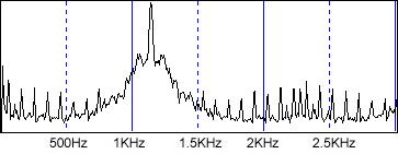
Un-filtered Audio spectra with heterodyne @1200Hz
More on the DSP subject on the net.
Here is a nice 'digest' about different DSP usage - Subject: DSP digest of answers
Type 1 - Built in DSP
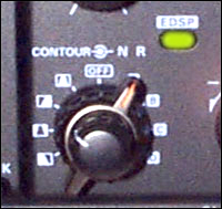
DSP-Controls on the FT-1000MP
Most modern HF(HAM)-Radio stations got some type of built in DSP function,- early models mostly work with the Audio Signal (Speaker-sound),- This make this type of DSP-future not al that different from whath can be done with the type-2 external DSP-units,- there is also some HF-Stations that got built in DSP that work with MF-Signals,- this is more sofisticated and more expensive
FT-1000MP / Built in DSP
- Sample - The DSP-Unit inside my Yaesu FT-1000MP is one of the first on the market,- it operates with Audio Signal. It got four pre-programmed audio-profiles called 'Contours' and four different levels of Noice reduction numbered 1 to 4,- to this day i do not know what this different levels of noice reduction actualy do,- the four audio-profiles however are:
1) BPF Band-Pass (Narrow) - QRM rejection
2) LCF Low CUT - High-Frequency emphasis
3) MFC Mid CUT - High & Low Frequency emphasis
4) HFC High CUT - Low Frequency emphasis
The EDSP portion from original FT1000MP manual (in 2.75Mb large .pdf file)
FT-1000MP DSP - Audio Spectrum analyses
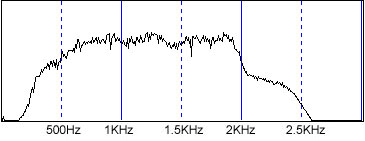
These Audio Spectrum diagram curves illustrates the DSP PASS-BAND Filter function in the FT-1000MP - other functions s.a. Random Noice reduction and multi-tone notch filtering is hard to show with diagrams.
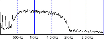
PASS-BAND Filter
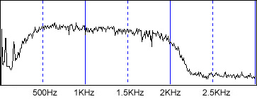
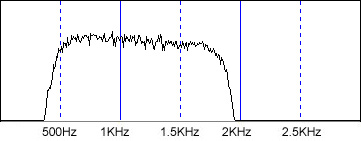
Audio OUTPUT with user 'Tailored' BAND-PASS (BPF) filter low-cut@ 320Hz and High-cut@ 2000Hz
Audio OUTPUT with user 'Tailored' BAND-PASS (BPF) filter low-cut@ 500Hz and High-cut@ 1800Hz
User 'Tailored' BPF Settings
On the FT-1000MP the BAND-PASS Filter (BPF) can be user 'Tailored' by mode. The default settings for SSB-Operation is NOT optimal when working on CB-Band with heavy QRM/Interference. I Prefere to set the BPF in a more 'Narrow' fasion. I use Low-Cut@ 380-420 and High-Cut@1800-2000. In the FT-1000MP this is set in Menu item no# 4-5 (SSb-HPF @ SSb-LPF)
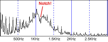
Auto Notch Filter
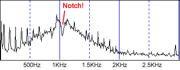
Audio OUTPUT with Auto notch@ 1200Hz
The Auto Multiple Notch Filter
After using my FT-1000MP for quite some time, i discover that the default DSP settings for the Auto Notch filter is set to 'Manual' - this does that the Auto Notch filter is DISABLED, also when the 'EDSP' is active! To fix this,- Enter menu item no# 2-9 and set the value to 'Auto-dSP' this does that the Auto Notch filter function is activated when both the 'EDSP' and 'Notch' switches is on.
The FT-1000MP uses a 16-bit NEC uPD77016 CMOS Digital signal processor
 Type 2 - External DSP-Units
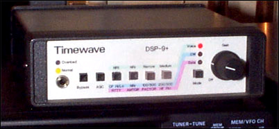
The TIMEWAVE DSP-9+
TimeWave DSP 9+ / External DSP
- Sample - The TimeWave DSP 9+ Digital Noice filter for amateur radio voice, data and CW operation. The DSP 9+ filters and reduces noice and interference to improve radio reception.
How it works...
The TimeWave DSP+9 makes use of computer controled digital signal processing technology to reduce Random/Tone and Noice interferance in incoming signals. It implement the computer controled algorithms to perform four basic functions:
1) Random noise reduction
2) Adaptive multi-tone notch filtering (Heterodyne TONE noice reduction)
3) Bandbass filtering
4) RTTY remodulation
Al these can be used one by one or al togheter in numerous combinations.
The signal is feed into the device and the characteristic of the signal and noise is analyced using a method called 'correlation'. The DSP+9 measures degree of correlation and filters out wanted signals from noise and Heterodyne tones, this is all done in 'real-time'.
Article with a test of the TimeWave DSP 9+
The Complete TimeWave DSP 9+ Operating Manual / Circuit Drawings (in 5.8Mb large .pdf file)
- TimeWave DSP 9+ - Audio Spectrum analyses
These Audio Spectrum diagram curves illustrates the DSP PASS-BAND Filter function in the DSP 9+ - other functions s.a. Random Noice reduction and multi-tone notch filtering is hard to show with diagrams.
PASS-BAND Filter
Audio OUTPUT in 'Medium' mode
Audio OUTPUT in 'Narrow' mode
Auto Notch Filter
Audio OUTPUT with Auto notch@ 1200Hz
- Manufacturers
NIR-12 Professional Dual DSP
TimeWave Corp. U.S.A.
TimeWave DSP-Units uses Processors from Analog Devices Inc.
Type 3 - Software DSP
The DSP-Filter Ver1.11 Software
The author of this software describe it as 'just experimental', I find it however quite useful, and verry easy to get 'up-and-running' - In my setup i use a 900MHz Intel-Celeron PC with 512Mb Ram, and an SB-Compatible 16-bit soundcard,- the program runs fine! with a merely noticeable delay. Finaly,- This software does NOT have any 'Auto-Notch filter' function.
There is however other more developed PC Software for HAM DSP-Purposes.
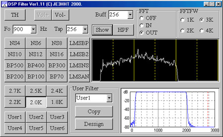
The DSP-Filter Ver1.11 Software
Notice that this software in 'Freeware', other software may not have this 'nice' licensing policy.
Download DSP-Filter Ver1.11 (281Kb .zip file)
The following text is included from the distribution .zip file
DSP filter Version 1.09J - June 18, 2000 JE3HHT Makoto Mori
Translated into English by JA7UDE Oba
This is a DSP filter tool using a PC with the soundcard. With this tool, you even can design various types of digital filters including adaptive filters. However, this tool is just experimental and will not afford the practical use for amateur ham radio.
You probably need a powerful CPU to make this tool run flawlessly.l In addition, you need a soundcard with the full-duplex mode.
I made this program just because of my own interest. As I was not quite familiar with the use of the soundcard, it still has substantial time lag from input to output and might not well work for CW. Needless to say, this program is freeware.
NOTE This Also!
Since this program intensively uses floating-point operations and is not well optimized, it will not run on a PC with a slow CPU.
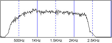
- Audio Spectrum analyses
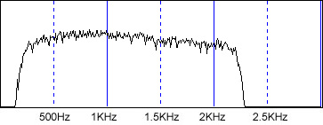
These Audio Spectrum diagram curves illustrates the DSP PASS-BAND Filter function in the DSP-Filter v1.11 software.
Audio OUTPUT with preset BAND-PASS filter 2.2KHz
Audio OUTPUT with user 'Tailored' BAND-PASS filter low-cut@ 500Hz and High-cut@ 1800Hz
*** End of page ***
<-- Go Back!