
- Antenna Tuner Kenwood AT-230 -
- Documentation -
- Technical data -
FACTORY SPECIFICATIONS
========================================
Frequency range....1.8--30Mhz
Max Power..........200W AM / 400W SSB

Dimensions.........
Weight.............

Manufactory........KENWOOD Inc. Japan
- AT-230 USAGE HINTS -
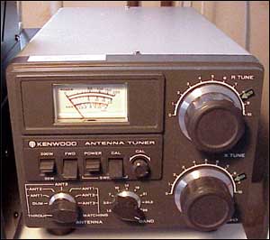
On the front you got four 'flip' switch selectors.
**With switch(3) In POWER(Up) position CAL/SWR switch(4),- is disengaged, it has no function and its position doesn´t matter.
**With switch(3) In SWR(Down) position 20/200W switch(1) and FWD/REF Switch(2),- is disengaged, thay have no function and its position doesn´t matter.
- Normal use (Power meter)
- Antenna switch in any 'THROUGH' position.
- POWER/SWR switch(3) in POWER (up) position.
- 200/20W switch(1) in desired position depending on power from radio.
- FWD/REF switch(2) in desired position depending of what you want to 'monitor'.
**With switch(3) In POWER(Up) position CAL/SWR switch(4),-
is disengaged, it has no function and its position doesn´t matter.
- Antenna switch in any 'MATCHING' position. (With connected antenna)
- BAND Switch on wanted Band
- POWER/SWR switch(3) in SWR position (Down).
- Cal/Swr switch in CAL position(UP)
**With switch(3) In SWR(Down) position 20/200W switch(1) and FWD/REF Switch(2),- is disengaged, thay have no function and its position doesn´t matter.
- Pretune for max RX noice
Use R-TUNE and X-TUNE Knob to tune and get as loud 'noice' from the speaker on your radio as possible. You should be able to get to a point where you clearly get the most noice. This is to get you as close to 'match' as possible, to be able to transmit for the final tune without any danger for your final transistors.
- Apply AM-Carrier (About 20-30W) from the radio,- Turn 'CAL' knob to get the meter
fully to the 'CAL' mark reading on the meter. (Increase power from radio if needed)
- Flip down the CAL/SWR switch(4) to SWR position and finalice the tuning procedure by turning the R-TUNE to get as low swr reading as possible on the meter, then turn the X-TUNE to get ewen lower swr, the turn R-TUNE again, repeat the procedure until your satified with the swr reading, you might have to do this 2 or 3 times.
- Antenna switch in any 'MATCHING' position. (With connected antenna)
- BAND Switch on wanted Band.
- POWER/SWR switch(3) in SWR position (Down)
- CAL/SWR switch(4) in CAL position (Up)
- Turn R-TUNE and X-TUNE for maximun RX noice
- Apply AM-Carrier - Turn 'CAL' knob to get the meter to the 'CAL' mark on meter.
(Increase power from radio if needed) - Flip down the CAL/SWR switch to SWR position and finalice the tuning.
Best regards
/73 de SM2YER Goran
*** End of page ***
<-- Go Back!
©1999/2000/2001/2002 SM2YER Goran