
- 0(Zero) dollar 12volt 8Ampere switch-supply -
Read this first!
This description is from 2001! The used PS-Supply is of the PC-AT type, this is not easy to get these days. I am about to update the text, but the only differance when using a modern PC-ATX Supply is that you don't need a main-switch (AC). you only need to use the 'PS-ON' signal lead, and connect it to ground (O) via a switch to turn the Power sypply on.
Description
In this article i describe How-To make an simple converting of an switched power-supply originally designed for use inside an computer,- the supply gives up-to 8Ampere current With the suitable voltage of 12Volt,- It is usable for your spare CB-Tranceiver or as i use it with my Galaxy in the Garage.
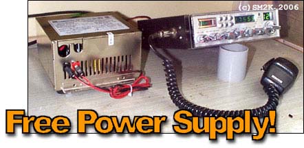
The ready made switch-supply at work!
Here with my garage-radio 'Galaxy Saturn'
Problems
Note! Always connect the sypply to a grounded wall-outlet. RFI interference from the computer graded switch supply may be a problem,- this is easy to solve with a RF-Choke Circuit
Do not operate the supply without any load for any longer period of time. The Switch supply is originally designed for constant load,- Don't forget to turn off the supply when not used (It gets extremely warm,- and may burn!!)
Depending of the supply used,- You may need to add 'dummy' load resistors to terminate the supply outputs not used (+5V/-5V/-12V) I did not have to do this.
Disclamer
You must understand that this article is provided on 'As-Is' basis,- the author or QSY11-Magazine can not take any responsibility for errors or omissions,- nor can any clames be made due to damages or other offence caused by use of information in this article. Al information is amed as 'just information'. The use of it is strictly in the hands of the reader, IT IS USED ON YOUR OWN RISK!!!,- Be careful when working with dangerous voltage,- always remove the power-cord from wall-outlet when working.
Origninal supply
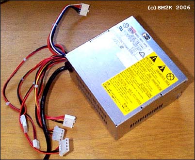
The original supply was 'adducted' from a scrapped PC-AT obtained from the local Computer dealer,- it was handed in for 'recycling'. (Cost=0$) I started whith opening it and cleaning it up,- it was full of dust! I used bottled compressed air.
Hint! - If you get your hands on an PC-ATX supply,- you find that the power-switch is already inside the sypply!
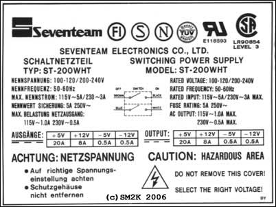
Make sure you start with a supply of good quality,- here i show a 'tag' from another PC-AT Supply,- it is quite usual that you should get the needed information,- such as rated current a.s.o. On this 'tag' i also get information on how to connect the main power-switch.
Next step was to solder away all un-needed cabled,- make a note before if the output voltage is not printed on the circuit-board
| Voltage | Color | Usage |
| +12V | YELLOW or orange | (Connect PLUS Lead here) |
| -12V | BLUE | (Not Used!) |
| +5V | RED | (Not Used!) |
| -5V | WHITE | (Not Used!) |
| 0 | BLACK | (Connect MINUS Lead here) |
At the connections for the YELLOW(+12V) and BLACK(OV-PTN) Leads i later on connected the output panel-jack (RED for PLUS and BLACK for MINUS) se later on in the text.
Needed stuff
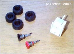
Abowe you can se the stuff used to compleete the supply.
A. A 2pol panel switch rated for 250Volt 2Ampere (Also abtained from the PC-Case)
B. Two panel jacks for the output (One RED for PLUS and One BLACK for MINUS)
C. Four rubber feets. (Optional - Also abtained from the PC-Case))
D. (If the Power Cord to your CB-Radio don´t hawe a fuse, you also need som type of fuse for the output, rated 6-8Ampere)
Put it together
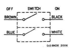
Time to make it work,- to be able to mount the power-switch i had to use a metal-saw and a file,- i simply made the whole where al the cables came out a little bigger, in order to fit the power switch,- the connection of the power-switch is the same as when it was originally mounted in the PC-Case
The Image show the power-switch connection
To 220V Input jack < -- > To Curcuit-Board
I also drilled two holes for the Output panel jacks. At the connections on the curcuit-board where the YELLOW(+12V) cords and BLACK cords (OV-PTN) previusly ware connected i now connected the output panel-jacks The RED one for PLUS and BLACK one for MINUS.
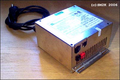
Front view
The switch-supply ready made, here shown with a standard PC-Power cord connected to the back of the supply.
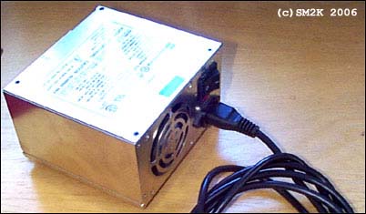
Back view
The Original power input jack is used to connect the standard PC-Power cord.
Time to test
When it´s al in place,- just put the cower back on and it´s ready for some testing. Connect a sutable load (Any 12V Load will do,- An old car-radio, An 12v Fan o.e. note! that it should not drain more than the rated current)
Hint! It might be wise NOT to use your CB-Radio when testing,- Use something unexpenssive in case something goes wrong!.
RFI Problems
In case you get problem with RF Interferance from the switched-sypply (Remember that it´s from a computer) You could need to make an final complemet to your new power-supply.
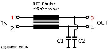
Schematic of the RFI-Filter
The RFI-Choke is made from an toroid-core,- also obtained from an PC-Supply,- on the toroid core i make a wounding out of standard 0,75mm2 plastic insulated power-cord leads,- first i wowen them together as a 'twisted-pair' and then wounded them on the core about 14 turns. After the RFI-Choke The remaining RFI is grounded to schassi with C1 and C2 - 1000pF cheramic capasitors.
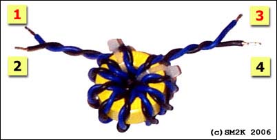
The RFI-Choke
Alternatives
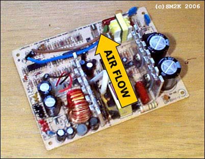
To use the supply in the shack you might which to remove the case and replace with something 'better looking',- this is not difficult. Remember that you ALWAYS Need to use a blower-fan, So remove the fan also and mount it so that the air-stream blows in line with the aluminum coolers on the curcuit-board.
<-- Go Back!
©1999-2006 SM2YER Goran