
- LOGOSTAR 6 -
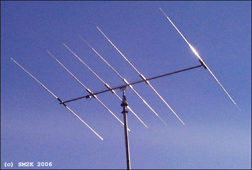
LOGOSTAR6 in the sky, an most excellent antenna.
- The "LOGOSTAR6" Antenna project -
The idea to use an transpose / cross-feed system to feed the RF-Signal onto several matched driven elements is the "key" to this antenna design.
- Why the LOGOSTAR6 -
The idea to use several driven elements is an efficient way of getting optimum phasing of currents in the antenna for high gain and an excellent beam pattern. This idea also gives you broader bandwidth compared to a conventional Yagi as a bonus.
The cross-feed system and the four matched drive elements, make this antenna excellent for CB-Radio DX from 26Mhz strait up to 28Mhz with less than 1:2 in SWR, without the need of any matching device (trans match o.e.)
How does this work - You might ask?. The theory behind this antenna design is real easy, I try to explain the fundamental ideas for the design first.
Number one: The RF-Signal on an specific frequency, example 26,5Mhz will automatically "prefer" to be emitted from the radial that is closest in match with the corresponding wavelength, in this case the longest driven element(Dr4) in the antenna construction.
Calculation: (300/26,5)/2 = 5,66m (Actual lenght of Dr4 = 5,768m)
Number two: The cross-feed system, feeds the RF-Signal with 180dgr off phase to the closest driven elements above and below in wavelength, this makes those element to act as parasite elements, this "phenomena" is caused by the fact that the cross-feed system, feeds the RF-Signal in the direct opposite phase to these elements.
Considering these two easy to understand statements, we got an antenna that is forced to switch to the best drive element according to our chosen frequency! (Within the range of 26 to 28Mhz that is!) Is this FANTASTIC or what! And it realy works to!
- Honors to the brains behind the theory -
The "brains" behind...
This antenna is designed using MS-DOS software "LOG-YAGI.EXE" version 1.6 by author Holger Granholm, OH0NC, Notice that this is shareware software, the registration fee is only $10.00us.
The "LOGOSTAR6" antenna design is based upon the theory for the "Swan Yagi", The "Swan Yagi" was invented by Oliver Swan, W6KZK and first described by Ed Tilton, W1HDQ in QST 10/69.
- History -
I received the original drawing for this designe from a guy in Hilversum, Holland. I built the first one in about 1985, and used it with great satisfaction for several years. When i moved to a new QTH the antenna was put on the 'shelf' for a couple of years when i solde it to an radio-friend, i dont know if he newer used it.
I got the great honer to build The second antenna for an werry enthusiastic DX-Friend.
- The actual antenna design -
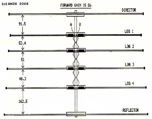
Details - The Antenna Layout.
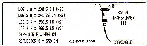
Details - Dimensions / Balun connections.
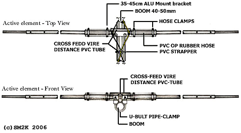
Details - Active element mounting bracket and cross-feed system - Top view
- Building the antenna -
I used an 40mm Dural-Aluminium tube as boom, the driven elements, the director and reflector is mounted on to the boom using one 50cm aluminum bracket and one U-bolt clamp for each element. The driven elements is insulated from the brackets with the PVC/Rubber hose, witch is cut into 20cm pices, the 40-50mm hose-clamps is used to tighten the driven element halfs onto the bracket. Distance (Gap) between the two element halfs on the driven elements is about 7.5cm at the center.
The director and reflector is POP-Riveted direct to the bracket, no insulation is needed in this case.
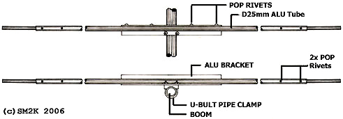
Details - Reflector and director element mounting bracket - Top view
- Tuning the elements -
If you measure the driven elements halfs carefully, no additional tuning is needed. This makes it possible to simply POP-Rivet the 25mm and 16mm parts for the element halfs together permanent. This is also the case for the complete director and reflector elements.
- Technical data -
Characteristics and performance. Operating Frequency Range 26 - 28.000 Mhz SWR less then: 1:1.8 High Frequency Center 27.500 Mhz SWR 1:1 High Frequency limit 28.200 Mhz SWR 1:2.3 Low Frequency Center 26.300 Mhz SWR 1:1 Low Frequency limit 25.800 Mhz SWR 1:2.2 Forward Gain 11.3 dBD Front / Back rejection ratio Better than 40 dB Front / Side rejection ratio Better than 25 dB
- Images -
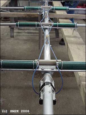
The Cross-Feed System...
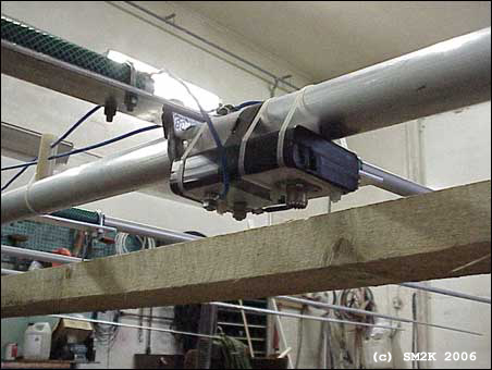
The Balun underneath the boom
<-- Go Back!
©1999/2000/2001/2002 SM2YER Goran